 English (UK)
  Deutsch (Deutschland)
Simcenter Amesim is a system simulation platform which allows you developing a Digital Twin of a product which behaves very similar to a real product.
Part I: Coffee machine principles, modeling methodology and a first set of components modeled
Motivation
Simcenter Amesim is a system simulation platform which allows you developing a Digital Twin of a product which behaves very similar to a real product. During the development phase of a product you can use Simcenter Amesim to
- define and verify an architecture of a product
- size the various components of which the product is assembled
- supply a proper physical plant model for control development
Since today’s coffee machines are complex mechatronic devices Simcenter Amesim is a valuable tool for you to master this complexity and balance all the dependencies between functions, parameters and design goals. Thus, you can reduce development costs and risk.
This is the first article in a series where I will show you how such a Digital Twin is being build.
If you would like to have a closer look into the Simcenter Amesim models I have developed, please do not hesitate to contact me. I will send you the models.
How a coffee-machine works
Modern coffee-machines can prepare coffee of various kinds. Espresso, Cappuccino, American Coffee represent only a small choice of possibilities.
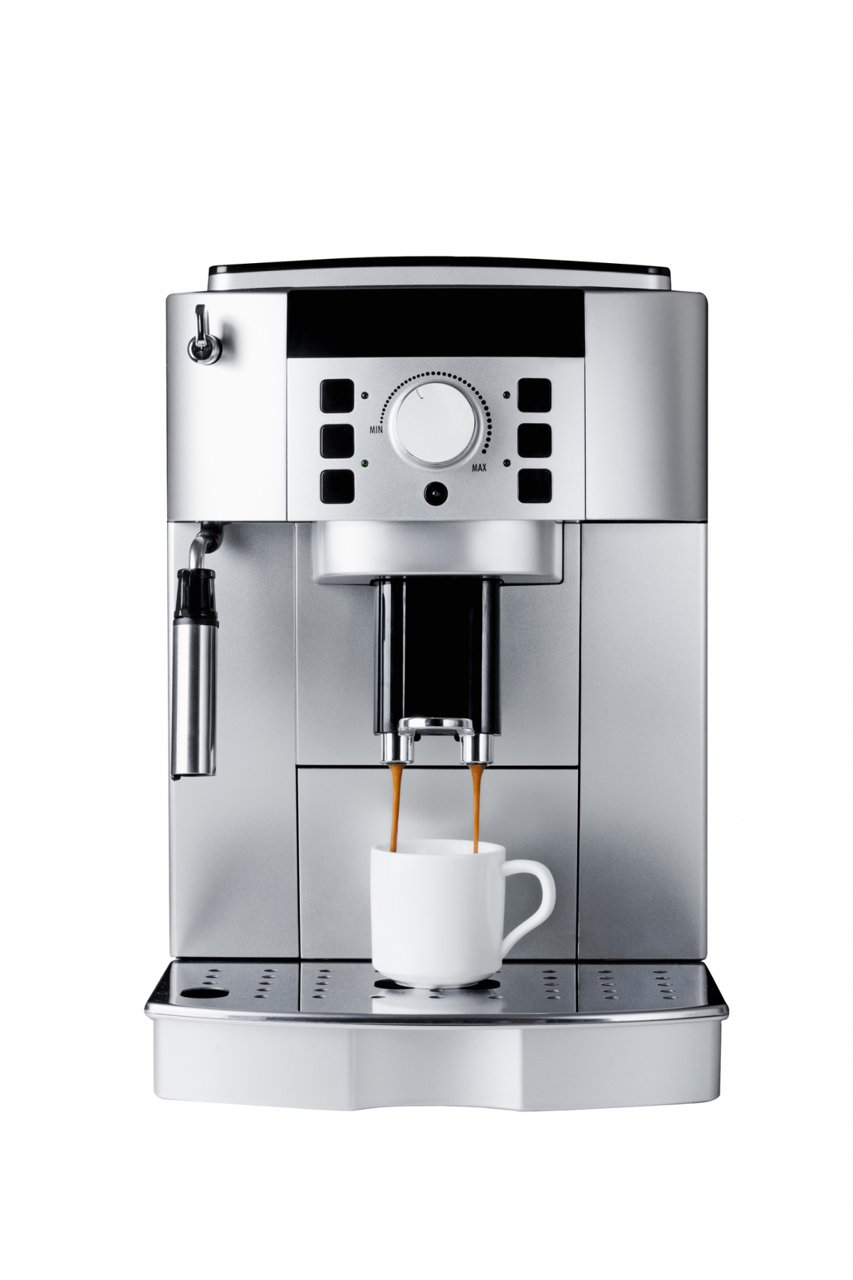
Figure 1 Siemens EQ9 coffee machine
Such a machine is built from components which are orchestrated by a control algorithm in order to prepare all the different types of coffee with a single machine. These components are:
- Various reservoirs for coffee beans, water, milk and sugar
- A crushing mill which grinds the coffee beans to coffee powder
- A device which transports the coffee powder into the brewer
- A brewer which presses hot water through the coffee powder
- A milk frother. Water steam sucks cold milk in a jet pump and mixes the hot milk with air in order to produce milk foam
- A device which puts sugar into the coffee
- A heater which supplies the brewer and the milk frother with heat
- A control device which controls each step of a brewing process. Dependent on the coffee choice:
- Offer a comfortable user interface
- When and how long should the different components operate?
- Which components must be used to prepare a certain choice of coffee?
- Which process parameters must be controlled and monitored?
- Monitor the amount of ingredients available in the reservoirs and give notice to the user if an ingredient must be refilled
- Monitor the amount of waste and give notice to the user if the waste reservoir must be emptied.
Building a Simcenter Amesim model
In this first article I will focus on modeling the individual components of a coffee machine.
Goals of this modeling exercise
I have several goals which I would like to achieve
- Build component models at an intermediate level of detail so that I can
- look into some physical behavior of the components
- assess energy consumption
- look at how many of a certain coffee variety is produced
- Build a simple control
- Build a statechart in order to mimic a user interface and program a simple control algorithm
Libraries needed
The libraries you will need depend on the type you have to model. It also depends on the level of detail you would like to model and if you need to concentrate on a certain component. For example, the electrical motors which drive the crushing mill or the pump (or pumps) can be modeled applying
- rotational speed sources
- simplistic electrical motors which supply a rotational speed and need some efficiency data
- electrical motors with simple or complex efficiency maps which are supplied with an electrical current
- with or without various levels of detail of the needed power electronics and speed/torque control
- with or without a controlled current source
For the model shown we will need the following libraries
- Signal and Control
- 1D Mechanical
- Thermal
- Thermal Hydraulic
- Two-Phase-Flow
- Electrical Basics
- Electrical Motors and Drives
Modeling approach
You should adapt a methodology which starts from simple, functional models of each of the above-mentioned components. You should verify their functioning before you increase the level of detail and before you switch from functional to physics-based modeling.
Figure 2 Modeling approach: start from simple models before adding details
After you have modeled each component you can start to assemble the complete coffee machine and add a control module.
In a last step you may add some interactive elements to your model in order to use the model as you are using your real coffee machine. A state chart will help you programming the control logic.
Modeling the individual components
I decided to model the following components: Crushing mill, heater, brewing unit, milk frother and control.
Crushing mill
The crushing mill is a simple device which transforms the coffee beans to coffee powder. However, the process itself is very hard to model and would need some very complex 3D FEM analysis in order to accurately model the cracking of the beans. And maybe it is simply not possible today to simulate that process.
For looking into the energy consumption of the coffee machine it is enough to model a rotational inertia with friction which is driven by a speed source or an electrical motor. The problem will be to parametrize the friction properly.
This is the model I have built for the crushing mill.
Figure 3 sketch of the crushing mill
It consists of a simple control which induces a constant rotary speed between 5s and 10s. I added a first order lag just to prevent the system from giving peak values in torque for example. The motor icon transfers the signal into a physical value and applies it to the inertia. The ideal rotary mechanical gear reduces the speed by a factor of 0.225. A rotational spring/damper element is included to meet the causality requirements. The inertia sees some friction (Coulomb and viscous friction). An energy sensor also is included. The results from the model you can study below.
Figure 4 results from the crushing mill
You simply can increase the complexity of the model by adding an electrical motor with voltage supply and speed control. This would be an approach to consider the dynamics of the motor and the heat generated in the motor. The temperature of the motor could be a process parameter which would have to be monitored.
Figure 5 crushing mill driven by an electrical motor
Here some exemplary results from this model.
Figure 6 results from the enhanced crushing mill
Heater
I have modeled the heater in two different ways also. The first model just uses heat-flux sources which can supply the brewing unit and the milk frother.
Figure 7 heater
The heat is switched between the two branches at 10s. Both heat-fluxes heat up a thermal mass which as a result heats up linearly.
Figure 8 result from simple heater model
For a more detailed approach I have used elements from the electrical basics library in order to model the heat generated in a resistive element from an AC source. This is how a heater in household appliances normally work.
Figure 9 heater modeled with elements from the electrical basics library
With this you may assess the influence of the time-varying heat load on the rest of the system. However, you will have to tackle two drawbacks of that approach. Since the AC is alternating at a frequency of 50 Hz computing time is high. The signal and its influence on the rest of components will be resolved by the solver. Secondly you will have to use lots of moving average elements to see how the system behaves from a more global perspective. If you do not use the moving average the given results will confuse you since it depends on the print interval you have chosen.
Figure 10 results from complex heater model at different print intervals (top: 0.01s, bottom: 0.0001s)
Brewing Unit
I started with a very simple model for the brewing unit. A pump, driven by a motor, a volume from the thermohydraulic library which can be heated, an orifice and two tanks acting as boundary conditions.
Figure 11 simple model of a brewing unit
The following results have been simulated.
Figure 12 results of the hot water tank
In reality, the hot water flows through the coffee filter first. After some time, a bypass opens so that pure water is delivered to the cup. I also wanted to have a first impression of what’s going on in the cup. Meaning what happens with the temperature of the coffee dependent from the initial temperature of the cup. I also included a simple two-point-controller which switches the heat load for the hot water tank in order to keep its temperature within a certain range. There is fluid property monitor in order to study their value dependent of the temperature level in the hot water tank. The resulting model is this.
Figure 13 brewing unit final model
First, lets have a look at the control signals.
Figure 14 control of the brewing unit
Since we have an initial temperature in the system of 20°C, the heater is operating from the beginning until the temperature in the hot water tank reaches 90°C. At 125s the water pump starts working. Hot water is going to be pumped towards the coffee filter. The temperature in the tank decreases so the heater starts heating again from 128s. The bypass valve opens at 135s and closes some time after the pump has stopped working.
This example shows you that you would have to wait at least 45s until the hot water tank reaches its desired temperature level in order to produce coffee. You also can see that you only must wait 7s after the bypass valve has closed for starting a new coffee production. These values will change when modifying the volume of the hot water tank. In this case the volume has been set to 0.2l.
Let’s have a look on the mass flows in the system.
Figure 15 mass flows in the system
The control valve connects the hot water tank with the coffee cup for the first 125s resulting in mp port P. Although the pump is at zero speed you see that there is a minimal mass flow from the beginning. This is due to decreasing water density in the hot water tank. The volume trapped in the hot water increases and leaves the tank towards the coffee cup. At 125s the pump starts working pumping water into the system resulting in an increase of mass flow through port P. You observe a second increase of mass flow when the heater starts again at 128s. At 135s the bypass valve opens, and a mass flow is observed at bypass port T. After the pump stopped turning at 140s there still is a small mass flow to be observed since the heater is still working. The blue curve shows you the evolution of mass in the coffee cup which is 120g at the end of the brewing process.
The next graph shows you the temperature of coffee and cup which corresponds to the explanations given above.
Figure 16 results from the coffee cup
Conclusion
A coffee machine can be modeled with Simcenter Amesim. This first part of the modeling journey has introduced to you a modeling methodology and the way I have modeled three components.
In Part II I will show you how the milk frother can be modeled and how all the four models are being integrated into a complete system.
Part III will cover the control part in more detail.
To learn more about Simcenter and to keep up with the latest from Dipolo, subscribe to our newsletter.